9 Results
View results:
Sort by:

Custom sections are often required in cold-formed steel design. In RFEM 6, the custom section can be created using one of the “Thin-Walled” sections available in the library. For other sections that do not meet any of the 14 available cold-formed shapes, the sections can be created and imported from the standalone program, RSECTION. For general information on AISI steel design in RFEM 6, refer to the Knowledge Base article provided at the end of the page.
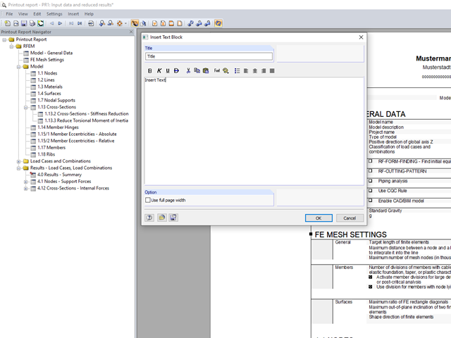
You can insert your own notes in the printout report. To do this, go to the printout report menu and click "Insert" → "Text Block."
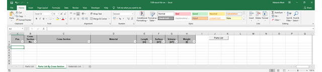
The parts lists give information about which and how many parts are necessary for creating a building. They form the basis for identifying the needs and purchasing the components. Parts lists can be created in design modules, such as RF‑/STEEL EC3, RF‑/TIMBER Pro, and so on. Furthermore, a customized parts list can be created with the RF-COM/RS-COM interface.
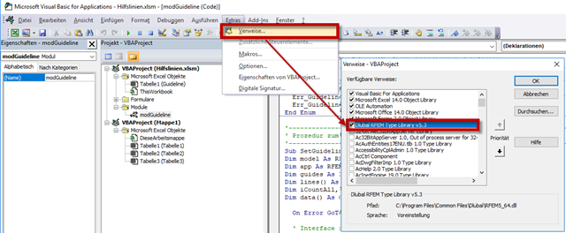
RF-COM/RS-COM is a programmable interface that allows the user to expand the main programs RFEM and RSTAB with customized input macros or post‑processing programs. A tool to copy and move selected guidelines in RFEM will be developed in this article. It is also possible to copy or move the guidelines to another work plane. VBA in Excel will be used as the programming environment.
You can change the content and appearance of a toolbar under "View" → "Arrange Toolbars Customized". This way, you can easily arrange and save frequently used commands in specific user‑defined toolbars. In addition to the default arrangement on the top of the screen, you can dock the toolbars on the left and right edges of the screen for a better overview.
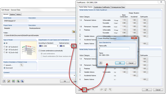
RFEM and RSTAB provide the option to create load and result combinations automatically according to the combination expressions defined in the standards. Partial safety factors and combination coefficients are specified in the standards or National Annexes. You can customize them as necessary and save them in a modified standard.
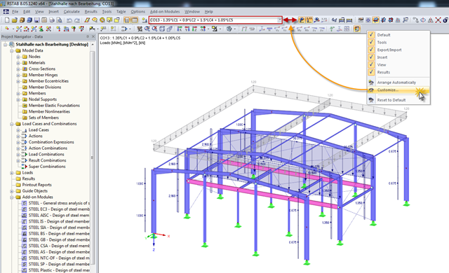
The RFEM or RSTAB user interface can be customized. The previous posts describe how to create toolbars and menu bars. Thus, this post focuses on the load case drop‑down list. This drop‑down list allows you to switch between individual load cases, combinations, and module cases.
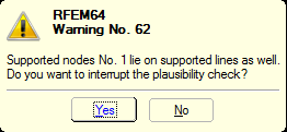
You can define nonlinear supports in RFEM and RSTAB. In RFEM, these are represented by nodal, line, and surface supports. Many customers contact us because of nonlinearities that are apparently not acting as desired. For example, there is a failing line support in a model. Since the structure is statically determined as supported, a linear nodal support is usually added. If the nodal support rests at the start or the end of a nonlinearly supported line, there is no clear definition of the degrees of freedom, so the nonlinearity cannot be considered properly. In this case, RFEM displays a warning message.
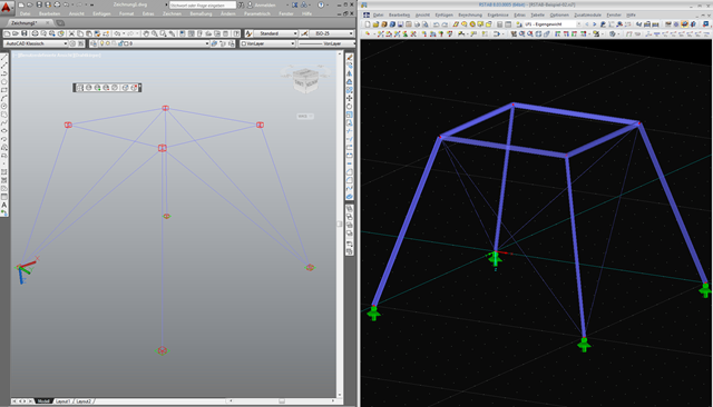
As requested by many customers, the nodes are now represented by cubes after export using the direct interface to AutoCAD or in a DXF file. If you want to reuse the AutoCAD data in RFEM or RSTAB, make sure not to import all the layers when specifying the settings for the import.